RTS stands for Random Telegraph Signal and is a very specific type of noise. The pixels that do show RTS effects seem to switch between different (more or less) discrete states. In most case they flip up and down between two signal levels. This RTS effect can originate through :
– dark current effects in the pixel itself, then the two flipping signal levels will be observed also as 2 RTS levels, or,
– the effect of a single trap in the source follower, then the two flipping signal levels in combination with the CDS can be observed as 3 RTS levels, without CDS they remain as 2 RTS levels.
How can these RTS pixels be characterized or located ? Actually the technique is very simple : because RTS pixels flip up and down between different states, they show a pretty large temporal noise. So what can be done is the following :
– grab several images (e.g. 100), with a relative long exposure time (100 ms or longer),
– calculate on pixel level the temporal noise that the pixel demonstrates in the images grabbed,
– rank all pixels according to the calculated noise, the pixels with the highest noise level come first and these are most probably RTS pixels,
– track the value of these suspected RTS pixels over the frames grabbed.
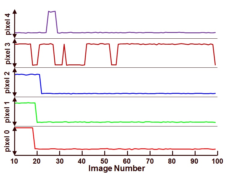
The result of this exercise is shown in the Figure 1(the data used for this measurement is different from the data used in previous blogs).
Figure 1 : Behaviour of a first group of five RTS as a function of time.
The images are taken with an exposure time of 2 s. On the horizontal axis the number of the image grabbed is shown (this can be seen as a time axis), and on the vertical axis the value of 5 RTS pixels is shown. (The pixel with the lowest number shows the largest temporal noise.) Pixel 0, 1 and 2 change only once over the time of (90 x 2 s =) 3 min. Pixel 3 is more lively and has several changes, notice that the time the pixel remains in the low state or the high state seems to be completely unpredictable.
Another group of five pixels is shown in Figure 2.
Figure 2 : Behaviour of a second group of five RTS as a function of time.
In Figure 2, pixel 5 is the one that attracts the attention : not only several transitions can be seen, but apparently the pixel switches between 3 states. It is not immediately clear whether the third state is due to :
– RTS of the dark current,
– RTS of the source follower, or,
– (most likely) due to a switching between two states somewhere half way the exposure time.
As can be learned, the RTS pixels can have very strange transition patterns, which are not predictable at all. This leads to the challenge of calibrating these pixels during the manufacturing of the cameras. In the case such a pixel behaves in the low state during calibration and in a high state during the application, the camera can show a white spot in the image captured …
Albert, 04-10-2012.

