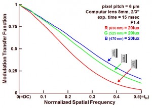
A new measurement result in the MTF-series is shown in this blog : the MTF of a monochrome sensor, but no longer with white light input, but with red, green and blue light. Some interesting observations can be reported.
In Figure 1, the results of the MTF measurement are shown.
 Figure 1 : Modulation Transfer Function of a monochrome device for various wavelengths of the incoming light.
It is quite nice to see the influence of the wavelength of the incoming light :
- The absorption coefficient of silicon for “red” photons, or photons with a lower energy, is relatively low. The absorption depth for light with a wavelength of 630 nm can reach a few microns. So part of the electrons generated in the silicon will be generated below the depletion region of the photodiodes, and before these electrons can get collected by the photodiodes, they need to “travel” in the neutral bulk/epi-layer. Because there is no electrical field present in these regions to guide the electrons to the right photodiodes, the chance that these electrons finally land in a neighbouring pixel is relatively large. In this way the contrast in the image is reduced, so is the MTF,
- The absorption coefficient of silicon for “blue” photons, or photons with a higher energy, is relatively large. The absorption depth for light with a wavelength of 470 nm is just a few tens of a micron. So most of the electrons generated in the silicon will be generated within the depletion region and the chance of diffusion of these electrons to neighbouring pixels is limited. The contrast in the image is not reduced by the effect described above for the “red” photons, neither is the MTF,
- The green light, with a wavelength of 525 nm, has an absorption coefficient situated between the red light and the blue light. So not surprising that the MTF for the green light is lying between the blue and red results.
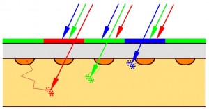
The effect explained here by means of the MTF measurements is also known as electrical cross-talk. The loss in contrast or loss in MTF is due to the diffusion of electrons. The effect is also illustrated in Figure 2.
 Figure 2 : Illustration of the electrical cross-talk.
Figure 2 shows a cross section of a hypothetical image sensor with an RGB filter. Illustrated is the fact that the “red” photons can penetrated much deeper into the silicon than the “blue” ones. This is the origin of the larger electrical cross-talk for the light having a longer wavelength.
To conclude a few numbers :
- Absorption coefficient for a “red” photon (630 nm) = 4000/cm, resulting in an absorption depth of 2.5 um,
- Absorption coefficient for a “green” photon (525 nm) = 10,000/cm, resulting in an absorption depth of 1 um,
- Absorption coefficient for a “blue” photon (470 nm) = 20,000/cm, resulting in an absorption depth of 0.5 um.
Albert, 19-04-2014.
Hi Albert,
There are quite many different reasons why different wavelength may have different MTF, even with a perfect lens, diffraction will lead to a lower MTF for long wavelength than short wavelength.
Another good way to measure the sensor influences on the MTF is to look at the transition from active to optical dark pixels. What better step response input could there be than a metal mask directly on your photodiodes?
Maybe you are right, but the definition of the light shield is not 100 % fixed and located at the right position, for sure not if you work with a BSI sensor. Also, the light shield is normally fully in parallel and aligned with the rows or the columns of the sensor, which does not allow you to apply a slanting edge method (will be discussed later).
This MTF performance with different wavelengths is for front illuminated CMOS and CCD imagers. Lenses also have similar MTF behavior with respect to wavelengths when their performance is limited by diffraction. However, the effect of electric field in these sensors should be reversed with respect to wavelengths for back illuminated sensors, specifically, for sensors with deep depletion, if I understand it correctly.