In a simple wording, the modulation transfer function or MTF is a measure of the spatial resolution of an imaging component. The latter can be an image sensor, a lens, a mirror or the complete camera. In technical terms, the MTF is the magnitude of the optical transfer function, being the Fourier transform of the response to a point illumination.
The MTF is not really the most easiest measurement that can be done on an imaging system. Various methods can be used to characterize the MTF, such as the “slit image”, the “knife edge”, the “laser-speckle technique” and “imaging of sine-wave patterns”. It should be noted that all method listed, except the “laser-speckle technique, measure the MTF of the complete imaging system : all parts of the imaging system are included, such as lens, filters (if any present), cover glass and image sensor. Even the effect of the processing of the sensor’s signal can have an influence on the MTF, and will be include in the measurement.
In this first MTF-blog the measurement of the modulation transfer function based on imaging with a sine-wave pattern will be discussed. It should be noted that in this case dedicated testcharts are used to measure the MTF, but the pattern on the chart should sinusoidally change between dark parts and light parts. In the case a square-wave pattern is used, not the MTF but the CTF (= Contrast Transfer Function) will be measured. And the values obtained for the CTF will be larger than the ones obtained for the MTF.
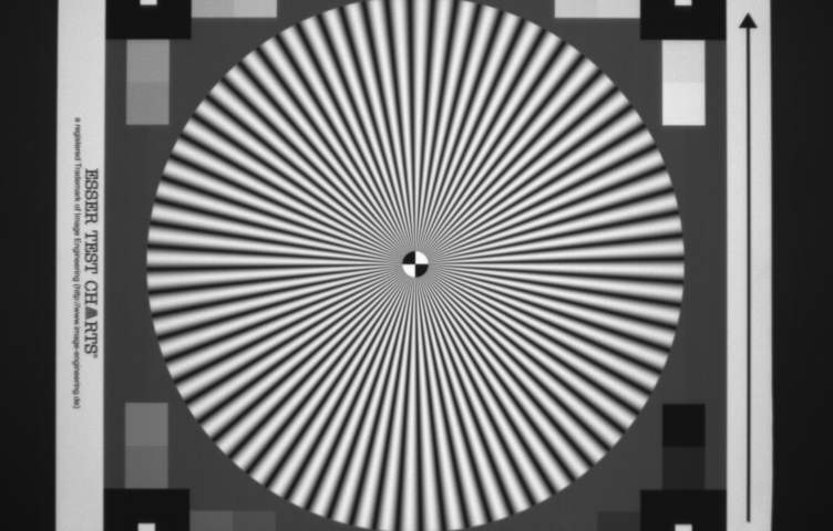
The method described here is based on the work of Anke Neumann, written down in her MSc thesis “Verfahren zur Aufloesungsmessung digitaler Kameras”, June 2003. The basic idea is to use a single testchart with a co-called Siemens-star. An example of such a testchart is illustrated in Figure 1.
Figure 1 : Output image of the camera-under-test observing the Siemens star.
(Without going further into detail, the testchart contains more structures than used in the reported measurement performed for the MTF.) The heart of the testchart is the Siemens star with 72 “spokes”. As can be seen the distance between the black and white structures on the chart is becoming larger if one moves away from the center of the chart. In other words, the spatial frequency of the sinusoidal pattern is becoming lower at the outside of the Siemens star, and is becoming higher closer to the center of the Siemens star. Around the center of the Siemens star, the spatial frequency of the sinusoidal pattern is even too high to be resolved by the camera-under-test and aliasing shows up. In the center of the Siemens star a small circle is included with 2 white and two black quarters. These are going to play a very important role in the measurements.
The measurement procedure goes as follows :
- Focus the image of the Siemens star, placed in front of the camera, as good as possible on the imager. Try to bring the Siemens star as close as possible to the edges (top and bottom) of the imager,
- Shoot an image of the testchart (in the example described here, 50 images were taken and averaged to limit the temporal noise).
In principle, these two steps is all one needs to be able to measure/calculate the MTF. But to obtain a higher accuracy of the measurements, the following additional steps might be required :
- Cameras can operate with or without a particular offset corrected/added to the output signal. For that reason it might be wise to take a dark reference frame to measure the offset and dark signal (including its non-uniformities) for later correction. In the experiments discussed here, 50 dark frames were taken and averaged to minimize the temporal noise.
- The data used in the measurement is coming from a relatively large area of the sensor and is relying on an uniform illumination of the complete Siemens star. Moreover, the camera is using a lens and one has to take into account the lens vignetting or intensity fall-off towards the corners of the sensor. For that reason a flat-fielding operation might be needed : take an image of a uniform test target, and use the data obtained to create a pixel gain map. In the experiments discussed her, 50 flat field images were taken and averaged to minimize the temporal noise.
- The camera under test in this discussion delivers RAW data, without any processing. If that was not the case it would have been worthwhile to check the linearity of the camera (e.g. use of a gamma correction) by means of the grey squares present on the testchart as well.
Taken all together the total measurement sequence of the MTF characterization is then composed of :
- Shoot 50 images of the focused testchart, and calculate the average. The result is called : Image_MTF,
- Shoot 50 flat field images with the same illumination as used to shoot the images of the focused testchart, and calculate the average image of all flat field images. The result is called : Image _light,
- Shoot 50 images in dark, and calculate the average image of all dark image. The result is called Image_dark,
- Both Image_MTF and Image_light are corrected for their offset and dark non-uniformities by subtracting Image_dark,
- The obtained correction (Image_light – Image_dark) will be used to create a gain map for each pixel, called Image_gain,
- The obtained correction (Image_MTF – Image_dark) will be corrected again for any non-uniformities in pixel illumination, based on Image_gain.
If this sequence is followed, an image like the one shown in Figure 1 can be obtained.
- Next the pixel coordinates of the center of the testchart need to be found. This can be done manually or automatically. The latter is done in this work, based on the presence of the 4 quadrants in the center of the testchart.
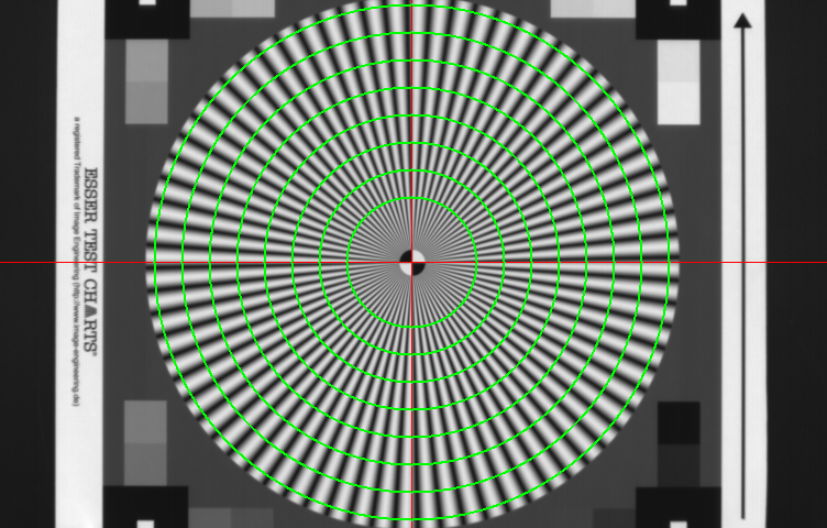
- Once the centroid of the testchart is known, several concentric circles are drawn with the centroid of the testchart as their common center. An example of these concentric circles on top of the testchart is shown in Figure 2.
Figure 2 : Siemens star with concentric circles (shown in green), with their centers coincides with the centroid of the testchart (red cross).
- After creating the circles, the sensor output values of the various pixels lying on these circles are checked. On every circle the pixel values change according to a sine wave, of which the frequency is known (72 complete cycles of the sine wave and it radius, in number of pixels, can be calculated). For each of the circles, a theoretical sine wave can be fitted through the measured data. Consequently for each circle a parameter can be found that corresponds to the amplitude of the fitted sine wave.
- In principle the MTF curve could be constructed, the only missing link is the value of the MTF for very low frequencies close to DC. This value can be found as the difference between the white values and black values of the four quadrants right in the middle of the testchart.
- Normalizing the obtained data completes the MTF curve : the calculated amplitudes of the sine waves are normalized with the signals of the four quadrants in the middle of the chart, the frequencies of the sine waves are normalized to the sampling frequency of the imager (6 mm pixel pitch).
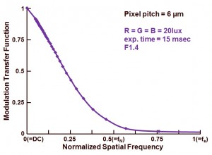
The outcome of the complete exercise is shown in Figure 3.
Figure 3 : Modulation Transfer Function of the camera-under-test.
As indicated in Figure 3, the MTF measurement is done with white light created by 3 colour LED arrays (wavelengths 470 nm, 525 nm, 630 nm). As can be seen from the curve, the camera has a relative low MTF, around 8 % at Nyquist frequency (fN). In theory an imager with a large fill factor can have an MTF value of 60 % at fN. But this camera is performing far away from this theoretical value. But one should not forget, this MTF measurement does include ALL components in the imaging system, not just the sensor !
Now that the MTF measurement method is explained, in the next blogs more MTF results will be shown and compared.
Albert, 20-02-2014.


The target mentioned is a Siemens Star, not a Siemens Start
Thanks, I corrected the “Start”.
Albert,
Thanks for the very informative article. What would be a typical MTF of the lens or the lens system? Does this sensor use microlenses?
More info will follow in the coming blogs. Albert.
Hi,
Thank you for a very good blog. Also wondering if you will look at the MTF of a pixel and how the Bayer pattern affects the sampling? Since color channels are not completely separated from each other.
Hi Per,
These subjects will be discussed, but when ? Time needed to perform the measurements is a problem at this moment, too busy with other projects. And recently I was facing some nasty issues with the hardware I am using …. Albert.
Hi Albert, and thanks for sharing your knowledge.
I have 2 questions regarding this post:
1) It looks to me that this method measures only the sagittal MTF. Is that correct?
2) You say that the pixel values around the green circle change according to a sine wave. I would have thought that it is the case if the resolution of the system under test is low but when it is high it would look more like a square wave from black (0) to white (1) but with rounded corner. I am correct?
Hi
Did you do the image processing and MTF analysis directly for the RAw image or did you first convert it into an RGB image?
Everything is done on the RAW data, taken directly from the sensor. Albert.