In the previous blog, the measurement of the Modulation Transfer Function by means of the Siemens star was explained. In this blog, this method will be applied to check out the effect of the lens F-number on the MTF.
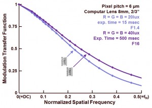
In Figure 1 the result of the MTF measurement is shown.
Figure 1 : Modulation Transfer Function for two settings of the lens F-number.
It is quite nice to see the influence of the F-number :
- a low F-number is referring to a large lens opening (= a lot of light goes to the sensor, a short exposure time is needed), and in that case the incoming light is reaching the sensor with a large chief-ray angle (= deviation from the normal),
- a large F-number is referring to a small lens opening (= much less light goes to the sensor, a long exposure time is needed), and in that case the incoming light is reaching the sensor with a small chief-ray angle (= almost perpendicular to the sensor).
Light that is perpendicularly reaching the sensor will suffer less from optical cross-talk in comparison to light that is reaching the sensor under a certain angle and is deviating more from the normal. More (optical) cross-talk does result in less contrast between neighbouring pixels, thus lowering the MTF for larger spatial frequencies. And this effect is observed in Figure 1 !
Next time something about colour and MTF.
Albert, 25-03-2014.

I’m confused…
With a really good / ideal lens, F1.4 is close to diffraction limited. With the airy disk formula ( http://en.wikipedia.org/wiki/Airy_disk ) the size of the point spread results in
x = 1.22 * lambda * f/d
with 500nm wavelength this would give
x =0,9 um for F1.4
x = 9,8 um for F16
Ok – now the real world computar lens is probably not ideal or high resolution – so with F1.4 much more blur is expected. But how much?
But how can you seperate the effect of the chief-ray angle from other aberrations? How do you know that the lens is actually in focus?
Looks like there are many more effects that need to be considered!
Michael, you are right, the cheap lens is not performing so well. (Quality has its price !)
About the focus : whether the image is in focus or not, plays a crucial role. For the measurements the lens was adjusted such that Moire effects were visible in the center part of the testimage. As soon as the image is out of focus, the Moire effects disappear immediately. So the presence of Moire or alias effects in the center of the Siemens testchart show you whether everything is in focus or not. More info will follow in one of the coming blogs. Albert.
Hi Albert,
the chief ray is usually defined as going through the center of the aperture stop and to the edge of the (image) field. As such, the chief ray angle is depending on lens construction and in most cases focus position, but not on the size of the aperture stop.
What you probably meant are the marginal rays, those are coming from the edge of the aperture stop.
You are 100 % correct in your explanation, thanks for your comment !